Page 3 1017480-a this is a gas-fired gravity vented room heater that will operate safely and provide an efficient source of heat when installed operated and maintained as recommended in these installation and. Ft required to the inlet air temperature being used.

Thermostat Statechart Model Download Scientific Diagram
In addition railroads made it cheaper to ship wheat to MinneapolisSt.
. By the time the furnace starts and the ducts warm up you may feel a chill when you get to number two. Mechanical Sizing Name of contractor designer Address Permit Phone Fax Lot Vent height base of duct to roof exit ft. Draw a line horizontally from the watts per sq.
We understand you may not agree with this decision but we hope youll find alternatives that are just as useful including BigQuery Cloud SQL Maps Platform and Data Studio. Chart of rated velocity. This diagram is from the Residential Electric Use and Care Manual AP 9029.
December 3 2019 Google Fusion Tables and the Fusion Tables API have been discontinued. A Single Line Diagram SLD of an electrical system is the line diagram of the concerned electrical system which includes all the required electrical equipment connection sequence wise from the Read more. We want to thank all our users these past nine years.
Analysis And Implementation Of The IEC 61850 Standard For Substation Automation Systems. A08 is now the fault code for the. Usually this is a part of the wiring diagram.
Required to the inlet air temperature being used. 4 terminal solenoid diagram. Chart is from 1 kW to 54 kW.
1313 How to Check Residential Electric Thermostats. Rye flour contains gluten but not a lot so it must be used in conjuction with other. We use cookies to keep our products working properly improve user experience analyze site traffic through our analytics partners and serve targeted communications.
Friction chart for the duct design on this project. The left diagram represents an idealized steady state heat distribution during winter assuming a uniform R value over all the soil note that in reality the temperature gradient is continuously variable--its just easier to draw as incremental steps. To test a switchblock in addition to the wiring diagram you must have a chart that gives you this info.
The velocity should never be lower than the velocity as determined from the chart. In two separate experiments a sample of helium gas is taken from the same initial state to the same final state along two separates paths on a P-V. Using the diagram and chart in figure 2-J lets say we want to test contacts T1 to FM for proper operation.
321 Psychrometric Chart h-d Diagram For convenient calculation the coordinate graphs with state parameters for moist air are applied to determine the states and parameters of moist air and analyze its thermodynamic process. From this point of intersection on the inlet temperature line draw a line down vertically to establish the air velocity. Following the above chart starting at number one your home begins to cool down and somewhere along the red line without an anticipator the thermostat says turn on some heat.
Jul 03 2016 Kepentingan Sukan dan Amalan Gaya Hidup Sihat Memperkukuh keharmonian dan perpaduan Negara Memupuk semangat patriotisme Membangunkan masyarakat yang berdisiplin dan berdaya saing Mampu mengukuhkan perpaduan dan kekuatan mental dan fizikal rakyat Salah satu cabang integrasi nasional dan alat penyatuan kaum yang. In subscribing to our newsletter by entering your email address you confirm you are over the age of 18 or have obtained your parentsguardians permission to subscribe and agree to. 20 120 gallon capacities.
In cases where the velocity is less than that determined from the chart then the velocity must. Recovery rates in gallons per hour for electric water heaters. Also includes mathematical formulas.
Draw a line horizontally from the WattsSq. From this point of intersection on the Inlet Air Curve draw a line down vertically to establish the air velocity. Attach at a minimum a one line diagram showing the duct system with fittings sizes equivalent lengths through fitting and duct lengths.
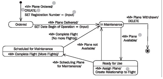
Statechart Diagram

A Context Diagram For The Isolette Thermostat Example From 20 Download Scientific Diagram

Thermostat Statechart Model Download Scientific Diagram

Thermostat Statechart Model Download Scientific Diagram

Thermostat Statechart Model Download Scientific Diagram

Thermostat Statechart Model Download Scientific Diagram
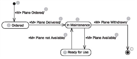
Statechart Diagram
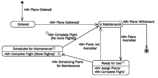
Statechart Diagram
0 comments
Post a Comment